L1: My first project
Categories:
My first BatSTEM project
What you will learn in this lesson
In this lesson, we will cover:
- Accessing the BatSTEM Cloud IDE programming interface.
- Connecting the ESP32 development board to the computer.
- Understanding the “setup” and “main loop” blocks.
- Controlling the internal LED of the development board.
Prerequisites
Before starting, you need to know your login details for the BatSTEM Cloud IDE platform https://ide.batstem.io.
Theoretical explanation
I want to know more!
In the upcoming lessons, you will learn how to create electronics and programming projects based on the ESP32 chip. This chip is an SoC (System on a Chip). It is called this because it integrates into a single device all the components needed to have a complete “computer,” including:
- A microprocessor for running programs and performing mathematical calculations.
- RAM to store programs to be executed and data needed by these programs.
- Storage for saving programs and data non-volatilely—meaning they are not erased when the device is disconnected from power.
- Input and output ports to connect external devices such as switches, LEDs, sensors, motors, and other complex electronics.
- Wi-Fi and Bluetooth connectivity to connect the device with mobile phones, tablets, or even the Internet.
Using the BatSTEM IDE development environment, we can design programs, store them in the ESP32, and execute them. After this process, the ESP32 can continue functioning even without being connected to a computer.
The development board we will use for our projects has two LEDs or small lights: a red one that lights up whenever the device is connected to power and a blue one that we will learn to control in this lesson.
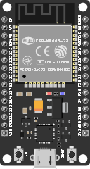
ESP32 development board with two built-in LEDs (red and blue)
Practical part
You will need the following materials:
- ESP32 development board.
- USB connection cable.
Connection diagram
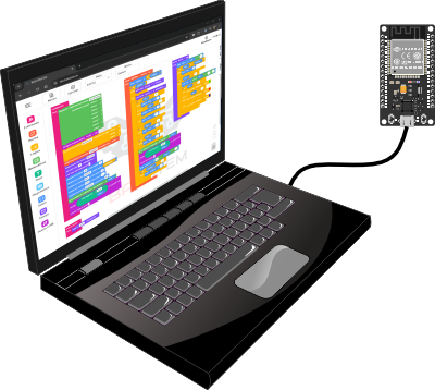
Connection between the computer and the development board
Step by step
- Connect the smaller end of the USB cable to the USB-C connector on the development board and the other end to a free USB port on your computer.
This connection between the development board and the computer will be required in all subsequent lessons, as it allows communication between both devices for programming and, in some cases, monitoring results.
Code
I want to know more!
To start developing your projects in the BatSTEM Cloud IDE, you need a user account. If you already have one, log in at https://ide.batstem.io. If not, create one at https://ide.batstem.io/register.
Once inside, you’ll see the structure of a new project or sketch, as shown in the following image.
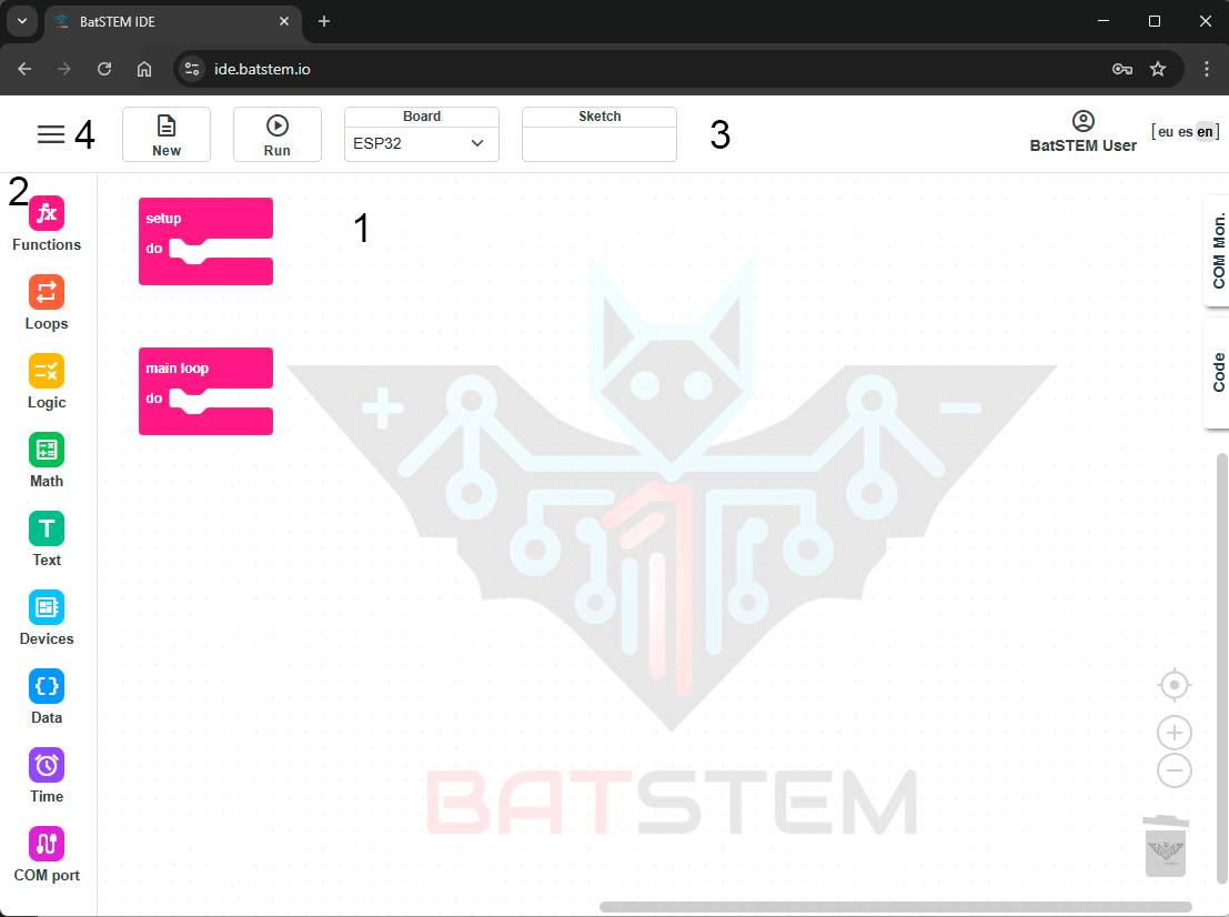
New empty project or sketch
If this is not your first time accessing the development environment, your last project may appear instead of a new one. If so, click New in the top toolbar to create a new project.
Within the development environment, you’ll find several sections:
- The workspace (1) is in the center, where we will place the blocks to build our sketch.
- The toolbox (2) is vertically on the left, containing blocks that can be dragged into the workspace to program the desired functions.
- The toolbar (3) at the top, with buttons to create a new project and execute it (load it onto the chip after translating the blocks into code that the ESP32 chip “understands”). Additionally, it displays information about the selected board model, the name of the sketch, and the current user’s name.
- The menu icon (4) in the upper-left corner lets you save projects, load previous ones, or delete unneeded ones.
- Additional sections, like the COM monitor, will be described in future lessons.
To successfully complete this lesson, understand the functions of the setup and main loop blocks:
- Blocks inside setup execute once right after the device starts, such as after clicking the toolbar’s Run button or connecting the USB cable. Use this block to define general device behavior during project execution.
- Main loop contains blocks that execute continuously in order from the first to the last, then restart indefinitely.
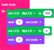
Turning the internal LED on and off
Now that we’ve understood the functions of setup and main loop, let’s create our first project. To make the internal LED blink, we will turn it on, wait, turn it off, wait, and repeat. We’ll use a one-second delay for this project.
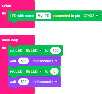
Build and run the following sketch:
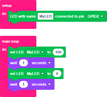
Step by step
-
Click the Devices icon in the toolbox. Select the green block for an LED device and drag it into the setup block. Ensure it’s set to “connected to pin GPIO2”. GPIO2 is the terminal where the internal LED connects on the development board.
-
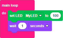
Add the block to turn the LED on. Click Devices. Since a defined LED now exists in the workspace, a new green block labeled “set LED” appears. Drag it into the main loop. Match its name with that in setup. Set the LED value to 100 (fully on).
-
Add a one-second delay block. Click Time and drag a “wait” block below the previous one. Set it to 1 second.
-
Add a block to turn the LED off, along with another one-second wait at the end of the main loop. Turn the LED off by using a “set LED” block with value 0 instead of 100.
-
Test your program by clicking Run in the toolbar. The project will compile, upload to the ESP32, and execute. If successful, the blue LED will blink on and off every second.
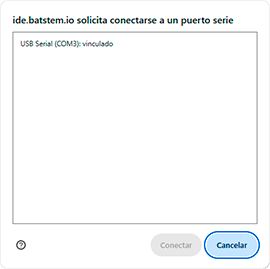
If this is your first time clicking Run on the toolbar, a pop-up window will appear asking you to select the port where the development board is connected. Choose the one named USB Serial and click the Connect button.
Additional exercises or challenges
- Modify your sketch so the LED blinks faster or slower.
Adjust the wait time in the two pauses.
One millisecond equals one-thousandth of a second, so 1 second equals 1000 milliseconds.
Summary of what you learned
- The development board is a self-contained “computer” that functions independently of a PC.
- We connected the development board to our computer.
- We accessed the BatSTEM Cloud development environment.
- We understood the roles of setup and main loop blocks.
- We created a sketch by dragging blocks from the toolbox.
- We compiled and ran our sketch on the development board.
Next steps
- Learn to connect an external LED in Lesson 2.