L2: The LED diode
Categories:
The LED diode
What you will learn in this lesson
In this lesson we will cover:
- What an LED or light-emitting diode is and how it works.
- Protection resistor. What it is and why it’s necessary.
- Prototype board. How it works and how we can use it to easily build circuits.
Prerequisites
To follow this lesson, you must have completed Lesson 1: My First Project. Additionally, the theoretical explanation will mention the concepts of voltage, current, and resistance, although it is not necessary to understand them in depth to complete the lesson.
Theoretical explanation
I want to know more!
What is an LED?
An LED (Light Emitting Diode) is an electronic device that converts electrical energy into light. The simplest LEDs have two terminals or “legs” and can emit light of a single color, which depends on the material they are made of. The most common colors are red, orange, yellow, green, and blue.
There are more sophisticated LEDs that can light up in different colors, which we will discuss in a later lesson.
Unlike a light bulb, which lights up regardless of the direction it is connected, an LED only lights up if it is connected in the correct direction because diodes are devices that allow current to flow in one direction but not the other. Therefore, we must pay attention when installing it in our circuit to connect it correctly. An LED is said to have polarity. A light bulb, on the other hand, does not have polarity.
Structure of an LED
In a light-emitting diode, we can distinguish 4 main parts:
- The LED chip (1) is responsible for converting electrical energy into light. It is made of materials known as semiconductors . The color of the LED depends on the materials it is made of.
- The capsule (2) serves to protect the chip and ensure the light it generates effectively reaches the outside.
- The positive terminal or anode (3) and negative terminal or cathode (4), which allow us to connect the LED to the rest of our circuit.
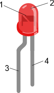
Main parts of an LED
It is important to distinguish between the anode and the cathode because, as mentioned in the previous point, an LED has polarity and must be connected correctly to function. The anode should be connected to a higher voltage than the cathode. We can use these rules to determine which terminal is the anode and which is the cathode.
- If the LED has one terminal longer than the other, the longer one is the anode.
- If the LED has a bent terminal near the capsule, this terminal is the anode.
- If the bottom of the capsule has a flat cut or notch, the terminal next to the mark is the cathode.
- If we look at the internal structure of the device through the capsule, we will see two small metal plates. The terminal connected to the larger one is the cathode.
Protection resistor
In certain electrical and electronic components, such as a resistor or a light bulb, the current passing through them is directly proportional to the voltage applied across their terminals. Components with this behavior are called linear components.
However, there are other components where the relationship between electrical current and voltage is not linear. This is the case with LEDs. An LED, being a special type of semiconductor diode, has a non-linear behavior.
This specific non-linearity of the diode causes a small change in the voltage applied across its terminals to result in a large change in the current flowing through it. If this current becomes too large, the diode may be damaged and stop working.
To prevent this, it is necessary to connect a resistor in series with the LED to limit the current that can pass through it. This resistor, called a protection resistor, will have a value that depends on the characteristics of the LED and the power supply voltage of our circuit.
In a later lesson, you will learn how to calculate the value of this resistor, but for the current lesson, we will use a 100 Ohm protection resistor.
The prototype board
Usually, an electronic circuit is composed of various components (chips, resistors, capacitors, diodes, transistors…) mounted and soldered onto a printed circuit board. Our development board is an example of a printed circuit board with different components soldered on it. These boards have two main functions: connecting the components together and providing the circuit with physical consistency to prevent damage.
However, they have a drawback in that they do not allow the circuit to be easily altered. Since we will need to assemble and modify our circuits constantly throughout this course, we will use a prototype board.
A prototype board consists of a board with holes that are internally connected in rows and/or columns. We can insert the terminals or pins of our components or small connection wires into these holes to quickly and easily assemble circuits.
The board included in the BatSTEM Basic Kit has 830 holes organized in two columns of 50 holes on each side, primarily used for connecting the circuit’s positive and negative power lines, and two blocks of 63 rows with 5 holes each. Both the holes in the side columns and those in each row are electrically connected.
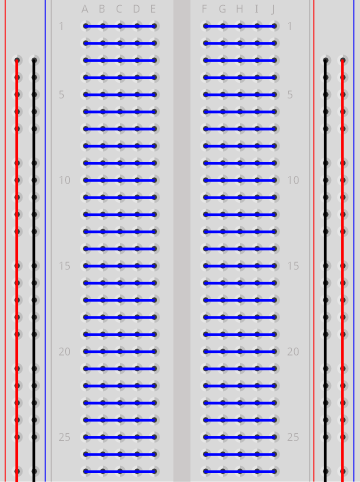
Internal connections of the prototype board
In the previous image, all holes joined by a line are electrically connected. Therefore, a terminal of an LED inserted into hole A-1 will be connected to a wire installed in hole D-1.
Practical part
You will need the following materials:
- ESP32 development board.
- USB connection cable.
- Prototype board.
- Red LED.
- 100 Ohm resistor.
- Connection cables.
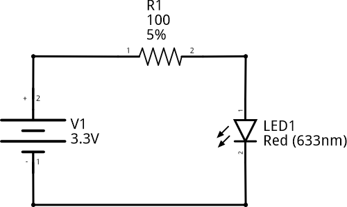
Electronic schematic
Connection diagram
In this lesson, we will use the development board solely to supply power to the LED. Therefore, it will serve as the power source shown in the previous circuit diagram. To make the connection easier, we will use the adapter board included in the kit.
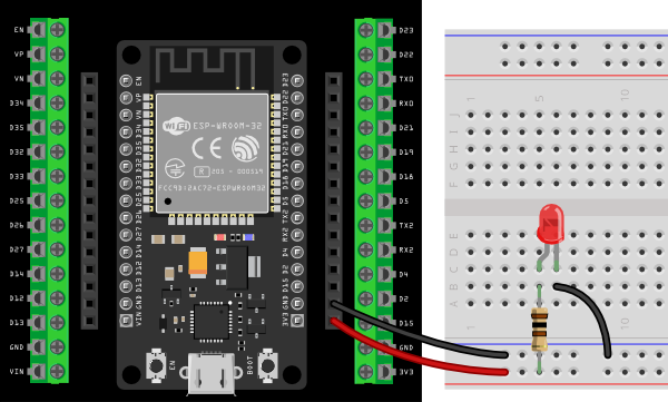
Connection of components on the prototype board
Step by step
- Place the development board onto the adapter board. Pay close attention to the positioning and ensure that the pins on the development board and the adapter board align correctly.
- Connect a red wire between the 3V3 connector on the development board and the red line on the prototype board. This way, the red line will be our positive voltage (V+) line.
- Connect a black wire between the GND connector on the development board and the blue line on the prototype board. The blue line will be our 0 volts, reference, or GND line.
- Connect the 100 Ohm resistor as indicated in the diagram. Note that one terminal is in the V+ line.
- Connect the LED as shown in the diagram. Ensure that the anode is electrically connected to the resistor.
- Connect a black wire between the cathode of the LED and GND.
- When everything is ready, connect the development board to the computer with the USB cable. If everything is done correctly, the LED will light up.
Additional exercises or challenges
- Remove the LED from the prototype board and reverse it, swapping the anode and cathode positions. What do you think will happen?
Summary of what you learned
- An LED is an electronic device that converts electrical energy into light.
- It is a non-linear device and only allows current to flow in one direction (from anode to cathode).
- To install it in a circuit, it needs a protection resistor to limit the amount of current passing through it and prevent damage.
- The prototype board allows us to create circuits quickly and easily thanks to its internal connections.
Next steps
- Learn how to control the external LED in Lesson 3.
Solutions to additional exercises
Show
What happens when the LED polarity is reversed?
As we have seen in the theoretical part, a standard diode or an LED only allows current to pass in one direction (from anode to cathode). If we reverse the polarity, the LED will behave like an open circuit, and therefore, the current will not flow, and the LED will remain off.