L3: The LED Diode (2)
Categories:
The LED Diode (2)
What you will learn in this lesson
In this lesson, we will cover:
- Controlling an external LED from the development board.
- GPIO pins: What they are and what we can use them for.
Prerequisites
To follow this lesson, you should have already completed Lesson 1: My first project and Lesson 2: The LED diode, as we will combine concepts from both to learn how to control an external LED connected to our development board.
Theoretical explanation
I want to know more!
In previous lessons, we saw that our development board features an ESP32 chip, which can be considered a complete computer on a single chip (SoC). One of the most exciting things we can do with this small computer is connect external elements and devices to interact with them through our programs.
We have several options for connecting devices to our development board, and in this lesson, we will explore the simplest one: GPIO pins.
What is a GPIO pin?
A GPIO pin (general purpose input/output) is a pin or contact on a chip whose behavior and function can be configured and controlled through our program. Among the parameters that can be configured, the most notable are:
- Direction: Determines whether the pin will be used as an input (to obtain information from the external device) or output (to send information or control the external device). For example, an external LED must be connected to a pin configured as an output, while a button or switch would be connected to one configured as an input.
- For outputs, the type of data they provide: digital (1 or 0), analog (a voltage value between V+ and GND), or PWM (a sequence of pulses with configurable width and frequency).
- For inputs, the type of data: digital or analog.
- For digital inputs, how the value is managed when the pin is not connected to V+ or GND (pull-up or pull-down, either internal or external).
The BatSTEM Cloud development environment provides low-level blocks to configure and control all these parameters, but it also offers higher-level blocks that allow us to control LEDs, buttons, and other devices without manually selecting these settings. During the lesson, we will learn to use both.
Our development board has a total of 34 GPIO pins, although not all of them can be configured with any combination of the described parameters.
Practical Section
You will need the following materials:
- ESP32 development board.
- USB connection cable.
- Prototype board.
- Red LED.
- 100 Ohm resistor.
- Connection wires.
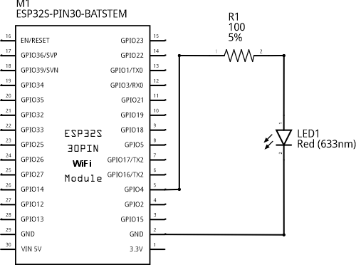
Electronic schematic
Connection diagram
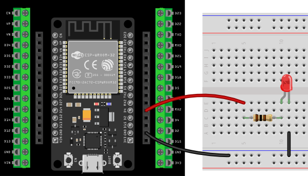
Connecting the components on the prototype board
Step by Step
- Connect a black wire between the GND connector of the development board and the blue line of the prototype board. The blue line will serve as our 0 volts, reference, or GND line.
- Connect a red wire between the D4 connector (GPIO4 pin) of the development board and any contact in the central blocks of the prototype board.
- Connect the 100 Ohm resistor so that one of its terminals is in the same line as the red wire you just placed, and the other is in a different line. This way, the red wire and the first terminal of the resistor will be electrically connected.
- Connect the LED so that the anode is in the same line as the second terminal of the resistor, and the cathode is in a different line.
- Connect a black wire between any hole in the line where you connected the cathode of the LED and the blue GND line.
- Once everything is ready, connect the development board to the computer using the USB cable. The circuit is now ready to start the programming section.
Code
We will develop two sketches that will make the external LED blink at half-second intervals, each using one of the two types of available blocks.
I want to know more!
As mentioned in the theoretical part, there are two types of blocks to control devices connected to GPIO pins:
- High-level blocks that represent devices such as LEDs or switches.
- Low-level blocks that allow us to configure and control the GPIO pin directly. Using these blocks, we can control any type of device, even if we don’t have specific blocks for it.
Turning the external LED on and off. High-level blocks.
Following the steps you learned in Lesson 1, build and execute the following sketch:
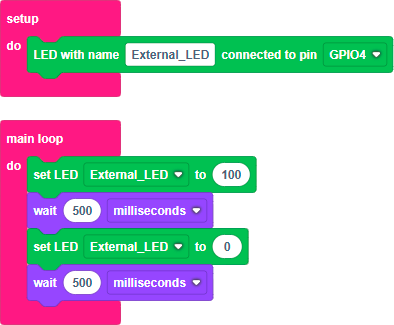
Step by step
- Click on Devices and drag a “Named LED” block into the setup block of the workspace.
- Assign a new name to the LED, for example, “External_LED”.
- Select the GPIO pin to which the LED is connected. If you followed the connection diagram, this pin is GPIO4.
- Click on Devices again and drag a “set LED” block into the main loop. Make sure the name in the block matches the one you specified earlier.
- Set the LED to a value of 100 (100% on).
- Click on Time and drag a wait block below the previous one. Specify 500 milliseconds.
- Add two new blocks similar to the previous ones. The only difference is the value to set the LED to, which in this case will be 0 (off).
When you need to add blocks similar to those already in the workspace, you can either drag them from the toolbox as before or duplicate the existing blocks. Right-clicking on a block opens a menu where you can select Duplicate. This option creates a copy of the block and places it in the workspace, so you only need to drag it to the desired location.
- Once your program is complete, click the Run button in the toolbar and wait for the sketch to compile and transfer to the development board. If everything went well, you’ll see the external LED turn on and off at half-second intervals.
Turning the external LED on and off. Low-level blocks.
Build and execute the following sketch:
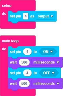
Step by step
- Click on Devices and drag a “configure pin” block into the setup block of the workspace.
- Specify pin number 4 and set it to output. Remember that we connected the LED to GPIO pin 4 and that, to interact with an external device, the pin must be configured as an output.
- Click on Devices again and drag a “set pin” block into the main loop. Ensure that you specify pin 4 and set it to ON.
- Click on Time and drag a wait block below the previous one. Specify 500 milliseconds.
- Add two new blocks identical to the previous ones but set the pin value to OFF.
- Once your program is complete, click the Run button in the toolbar and wait for the sketch to compile and transfer to the development board. If everything went well, you’ll see the external LED turn on and off at half-second intervals.
Additional exercises or challenges
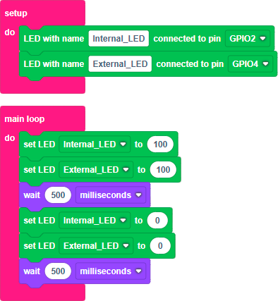
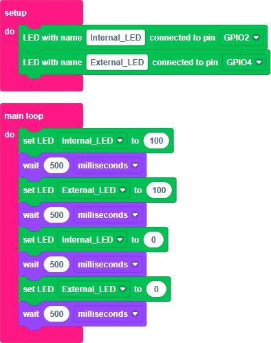
- Combine what you learned in this lesson and Lesson 1 to develop a sketch that makes both the internal LED of the development board and the external LED blink simultaneously.
- Modify the previous sketch so that the LEDs blink in antiphase. That is, when one turns on, the other turns off, and vice versa.
- Modify the sketch so that both LEDs follow this sequence with a half-second delay between each change:
- Turn on blue.
- Turn on red.
- Turn off blue.
- Turn off red.
Summary of what you’ve learned
- We have learned to control an external LED from our development board.
- We have seen what GPIO ports are and how they can be used.
- We have used the two types of blocks available in the BatSTEM Cloud environment to control external devices: High-level blocks and low-level blocks.
Next steps
- Learn to control the brightness of the LED in Lesson 4.